| “This site contains affiliate links for which OEMDTC may be compensated” |
SUBJECT:
FORTE LOCK CONFIRMATION INOP WITH REMOTE START ACCESSORY
Some remote start equipped Forte’s may not indicate that the doors have been locked. The customer may state that the vehicle will not flash the hazard lights or sound the horn when locking the doors with the transmitter. As designed, the vehicle should flash the hazard lights and sound the horn after pressing the lock button two (2) times within five (5) seconds.
If this concern is occurring, verify if it is related to the remote start control module by checking the position of the overhead interior light switch. If the switch is in the “OFF” position, move the switch to the “DOOR” position and retest the system. If the system performs properly, refer to the procedure below to address the customer’s concern.
NOTE: Record customer’s radio presets before disconnecting the negative terminal from the battery.
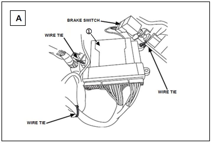
- Locate remote start control module 1 under the driver’s side dash near brake switch as shown in Figure A.
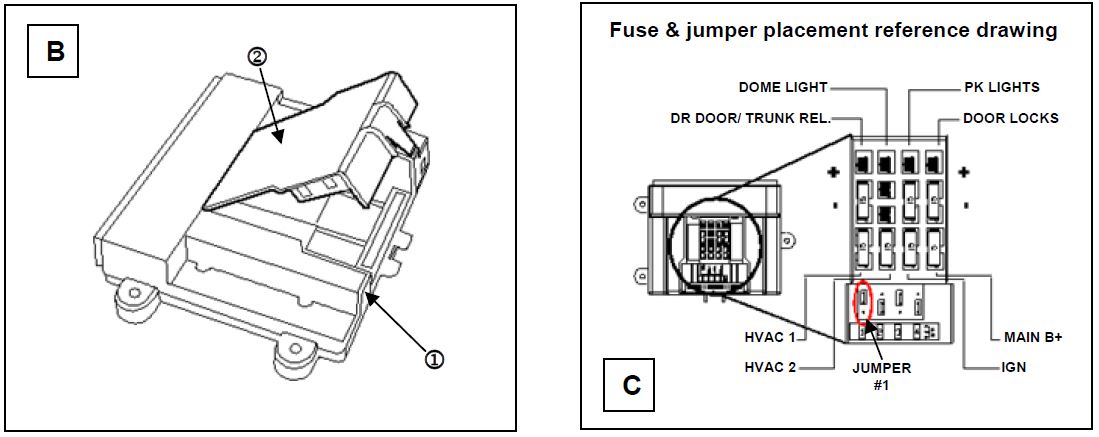
- Carefully remove the DNA/Software Card 2 from the control module 1 as shown in Figure B.
- Locate jumper # 1 on the control module and reposition it to the “UP” position as shown in Figure C.
- Carefully reinstall the DNA/Software Card onto the control module.
CAUTION Use care to assure that both rows of the DNA/Software Card multi-pin connectors are aligned and seated properly.
- Unplug the 24‐pin connector from the remote start control module.
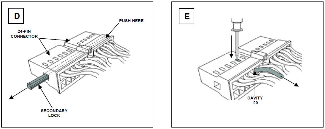
- Using a scratch awl tool, carefully push out the secondary lock from the smaller of the two (2) ends until it is completely removed from the 24‐pin connector (Fig. D).
- Using a scratch awl tool, carefully push down the terminal metal tab securing the Yellow wire located in cavity twenty (20) (Fig. E).
- Remove the Yellow wire by gently pulling outward as shown in Figure E.
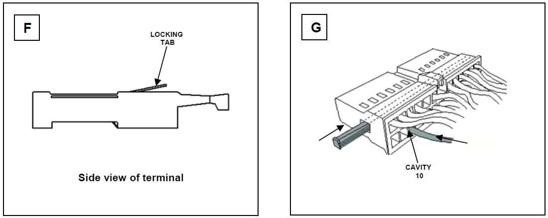
- To ensure proper re‐locking, carefully push the metal locking tab, located on the top of the terminal, away from the terminal body (Fig. F).
- Insert the Yellow wire until it “clicks” into place in cavity ten (10) (Fig. G).
- Reinstall the secondary lock as shown in Figure G.
- Reconnect the 24‐pin connector onto the remote start module.
SYSTEM POWER UP
Turn the ignition key to the “ON” position. Reconnect the negative battery cable. Turn the ignition key to the “OFF” position.
FUNCTION CHECK
Refer to KGIS > Publication > Accessory info for vehicle specific remote engine start installation instructions and a complete list of functions, to be verified, before delivering the vehicle.
NOTE: Reprogram radio pre‐sets as recorded earlier.
 Loading...


